
This article is written from a Finnish design point of view and is intended for ventilation system balancers and testers. It may also be of interest if you’ve ever wondered how a designer thinks about duct system design and balancing, or how a system is dimensioned.
Nowadays, practically all design work is carried out using software1 that handles system balancing and dimensioning according to given parameters. The designer no longer manually calculates pressure losses or airflows but instead defines the boundary conditions for the program, which then sizes the duct system and balances the airflows. This has somewhat led to a situation where the designer may forget the fundamental principles of system balancing, and as a result, balancing on-site doesn’t always go smoothly.
General Notes on Measuring and Balancing
In Finland, ventilation system measurement and balancing work can currently be performed by anyone. The Finnish HVAC Association (SULVI) offers training in ventilation measurement and balancing, after which it’s possible to apply for SULVI’s certification in balancing work. SULVI’s certification is, to my knowledge, the only way for an external party to verify a person’s competence in balancing. In other words, there is no official vocational qualification required for balancing work.
There are a few methods for balancing ventilation systems, of which the proportional balancing method has generally been considered the best and most effective. SULVI’s training and, for example, Esa Sadberg’s HVAC engineering textbooks2 both refer to the proportional balancing method.
Proportional Balancing
This article won’t go through the full principles of proportional balancing but will instead focus on details that may be useful for professionals already familiar with the method.
Proportional balancing is based on the reference valve. The reference valve is the valve in the branch where air has the most difficulty reaching, it’s also referred to as the most difficult route. In balancing, the reference valve should end up with the lowest pressure loss in its branch once balancing is complete. This minimizes the total pressure loss in the system. Traditionally, balancing technicians have had to find the reference valve in each branch either through experience or trial and error before balancing could begin.
Below is an image from a design software (Figure 1). The duct system shown isn’t from any real project; it was drawn solely for this example. Notice the pressure losses shown along the dimensioning lines. Experienced balancers know that the pressure losses shown in HVAC drawings are not values that can actually be measured on site. These design pressures are primarily used for internal validation of the design. However, they do offer one practical advantage on site: they directly reveal the locations of the reference valves.
The design software (MagiCAD for AutoCAD) sizes the duct system using the proportional balancing method. Of course, the software can handle other methods as well, but in a basic case—unless the designer specifies otherwise—it simulates the outcome of proportional balancing. As a result, each branch has a valve with a pressure loss equal to the minimum pressure loss defined in the software. In the example below, this minimum value is set to 10 Pa (marked in red). Correspondingly, the control dampers have a separate minimum value, which in this case is also 10 Pa (marked in blue).
Those minimum-pressure-loss valves (red 10 Pa) are the reference valves for each branch. Therefore, if the ductwork is built according to the design, these valves can be used directly as references during balancing. Similarly, after the branches are balanced, the reference damper can be identified (blue 10 Pa).
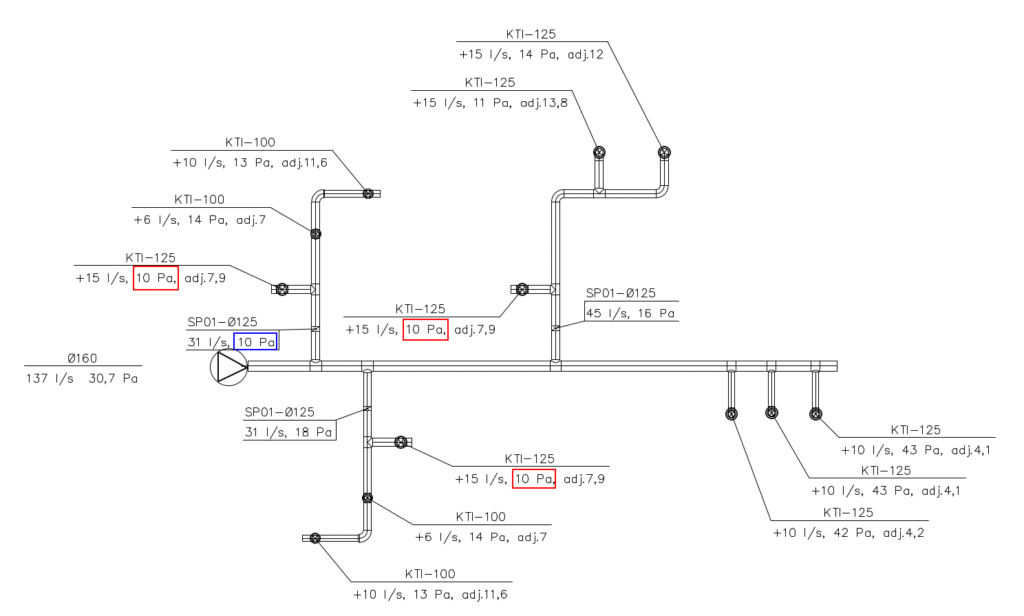
Figure 1
The Role of Pressure, Balancing vs. Design
If you’ve taken SULVI’s measurement and balancing training, you’ve heard of the lowest pressure level. SULVI’s training instructs that the pressure at the reference valve should be adjusted as low as possible while still staying within the valve’s adjustment range. This minimizes the system’s overall pressure level, reducing the fan’s workload and avoiding unnecessary energy consumption due to excessive pressure losses.
However, there’s a small pitfall here. While pressures are always designed to be as low as possible, some air distribution methods require somewhat higher pressures. The choice of air distribution method is based on the indoor climate class selected for the spaces. Based on the function of the space and its indoor climate class, the designer chooses a suitable air distribution method.
The most common and well-known air distribution method is mixing ventilation. In Esa Sadberg’s HVAC Engineering, Part 2: Air Conditioning System Design, he states:
“In mixing ventilation, the goal is to mix clean, possibly conditioned supply air as efficiently as possible with room air.”
The book also notes that one of the defining characteristics of mixing ventilation is that the outlet velocity of supply air from the diffuser is relatively high. Higher discharge velocity ensures better mixing, which cannot be achieved with a low velocity. In other words, in most Finnish air distribution systems (based on practical experience rather than measured data), the supply air is intentionally given a certain momentum to promote mixing.
This has significant implications for pressure, especially when the supply air terminal device does not include a plenum box.
The Role of Pressure in Supply Air Terminal Devices
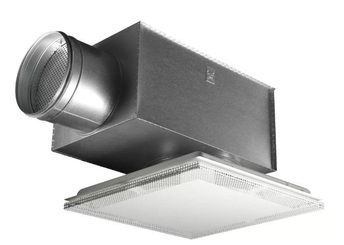
If the terminal device includes a plenum box, pressure doesn’t affect the throw or velocity. In that case, the faceplate of the diffuser has no adjustable components, and the airflow velocity is entirely determined by the airflow rate, which is adjusted in the plenum before the faceplate. Thus, pressure at the reference valve can safely be kept low.
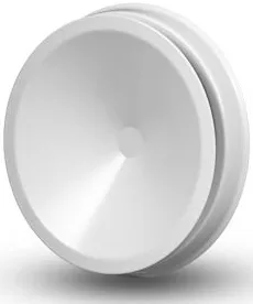
If the terminal device does not have a plenum box, the situation is different. In such devices, the airflow is often adjusted by changing the device geometry. When the geometry changes, the pressure loss also changes, which in turn affects the airflow rate. If such a device is adjusted to operate at a very low pressure, the outlet air velocity will also be low. These devices can therefore deliver the same airflow at multiple combinations of pressure loss and velocity.
The designer selects the device and its setting so that the air velocity is sufficient to achieve proper room air mixing. Therefore, the balancer should always take into account the device setting specified in the design documents. Conversely, the designer should include the intended setting or at least an indicative pressure loss in the design drawings.
- Typical software used includes MagiCAD, Revit, etc. ↩︎
- Esa Sadberg: Ilmastointitekniikka, Parts 1 & 2. ↩︎
Share this post: